


Associate Editor
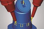
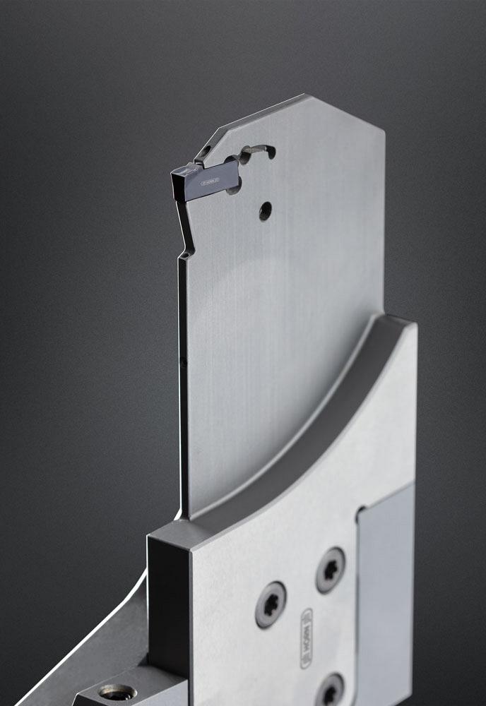
Square blades provide stability and vibration-free performance with full support underneath by an adapter at the bottom as well as the back end of the blade. Iscar
As one of the last operations to be performed on a component, parting off needs to be done correctly to ensure all that machining time and effort isn’t in vain. This operation tends to be a small fraction of a component’s overall machining time and is sometimes overlooked when it comes to finding efficiency and time savings.
"In many shops, the No. 1 tools that break and can be found in the scrap bin are parting off tools," said Edwin Tonne, training and technical specialist, Horn USA Inc., Franklin, Tenn. "Parting off is one of the riskier operations, so many operators tend to be conservative when it comes to feed rates and can be resistant to take parting-off operations outside their comfort zone. It’s one of the most demanding operations, but high-feed parting can make sense for many shops."
High-feed parting off can be done in X- and Y-axis setups. Shops should explore which option makes the most sense and follow best practices to ensure that parting-off operations are done correctly.
Traditional parting off is often done with an X-axis setup. However, to move into high-feed parting off, there are a few things to consider.
"First and foremost, does your machine have the capability to handle high-feed parting?" said Ashok Guruswamy, product manager, grip/turn/thread, Iscar Tools Inc. Canada, Oakville, Ont. "It needs to be able to work with high-feed inserts and tools, but it also has to have the rigidity to support the high-feed parting system."
In standard high-feed parting off, stability is essential. It’s important to work with the shortest setup possible from where the tool is clamped to the tip of the tool.
"There are lots of newer geometries that specifically work with high feeds," said Tonne. "These geometries tend to be more robust and in order to get that stability, a solid cassette system is a good starting point."
High-feed parting inserts are designed for specific material groups. However, they all are designed with a robust cutting edge structure which provides extra strength to the cutting edge along with a cavity for ease of chip flow, which is essential for parting-off operations.
"Square blades provide outstanding stability and vibration-free performance with full support underneath by an adapter at the bottom as well as the back end of the blade," said Guruswamy. "Standard conventional parting methods don’t have the same support system. A reinforced tool block along with a square blade provides high blade stiffness and rigidity, allowing high feed rates and increased productivity."
High-feed parting inserts require a certain feed rate to successfully part off. And while some operators tend to be conservative when it comes to parting off speeds and feeds, these inserts are designed to excel with a feed rate that is equal to or higher than the K-land.
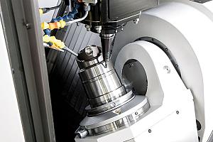
Y-axis parting off offers a blade stiffness that's 600 per cent better than X-axis blades, as the direction of the cutting forces go up the length of the blade rather than across the width or height. Sandvik Coromant
"High-feed parting inserts include a built-in K-land and a cavity designed for ease of chip flow that enables higher feed rates," said Guruswamy. "The K-land deflects chips away from the workpiece and cutting zone, so if the feed rate is less than the K-land, this can hamper chip control and potentially render the operation ineffective. It’s important to follow the literature for proper speeds and feeds to ensure that high-feed parting off operations are done effectively."
Guruswamy added that the parting tool should be mounted 90 degrees perpendicular to the spindle axis, and tool centre height should be aligned to the spindle axis. It also is important to indicate the tool holder to 0.004 in. over 4 in. maximum, but for optimum setup, indicate to 0.001 in.
"The cutting edge needs to be parallel to the workpiece to ensure proper clearance for the trailing cutting edge," he said. "The smaller the deviation, the better the tool performance."
For those looking to move beyond the more traditional parting-off setup, Y-axis parting off offers some benefits.
"For the most part, Y-axis parting off is not always common because of machine limitations," said Tonne. "Some machines have the capability to maintain rotation speed as the tool moves towards centre on the Y axis."
For Y-axis parting off, it is necessary that the machine has the capability to reprogram the Y axis to ensure that it can meet the speeds and feeds to achieve that operation.
"Y-axis parting off tends to offer greater setup stiffness," said Kevin Burton, turning product and industry specialist, Sandvik Coromant Canada, Mississauga, Ont. "A multitasking machine offers the Y-axis option over a standard XZ option. Similarly, lathes tend to have standard XZ axes but some are equipped with a Y-axis option on the turret. This is something more typically seen on newer, more modern machines. But with Y-axis parting off, higher feed rates can be applied."
An advantage of Y-axis parting off is that the blade stiffness is 600 per cent better than X-axis blades, as the direction of the cutting forces go up the length of the blade rather than across the width or height. This allows for significantly improved bending stiffness, meaning increased stability and limited, if any, vibration.
Regardless of whether it’s an X- or Y-axis setup, there are some best practices that can help ensure high-feed parting off success.
"Y-axis [parting off] allows the tool to come in from underneath the workpiece, and because of the rigidity the setup allows for parting off larger-diameter components," said Burton. "You would use the same inserts and follow similar success factors that you would with traditional parting off. However, we also are seeing more toolholders and options on the blade to allow for shops to take better advantage of Y-axis parting off."
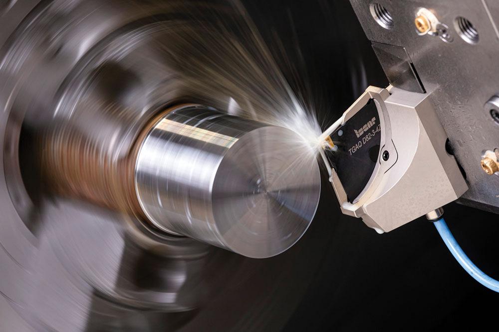
Not all geometries out there are acceptable for high-feed parting so it’s important to choose an insert with a very strong, robust front edge. Horn USA
Burton noted that there are some offsetting requirements for this type of application, which is not required for X-axis parting off.
"There are a couple of manual offset adjustments needed," said Burton. "Because of the precision needed for high feed to be successful, once the tool is set, do a trial run and run the program dry to make sure that the tool is going to centreline. Once the offset is correct, the operator can increase the feed rate and perform Y-axis parting off operations."
Regardless of whether it’s an X- or Y-axis setup, there are some best practices that can help ensure highfeed parting-off success.
"In any situation, no matter how the insert is held, the insert edge has to withstand the higher pressures," said Tonne. "Whether it’s Y-axis parting off or standard high-feed parting off, an insert with a very strong, robust front edge is needed. Not all geometries out there are acceptable for high-feed parting, so be careful to make the right selection."
Feed is very much related to chip formation, and newer geometries designed for high-feed parting will focus on producing good chip formation. The higher the feed, the more likely the operation will have poor chip control. A parting blade, for the most part, has a long overhand in relation to other operations, so it is prone to vibration.
"To maintain a high surface quality and rigidity, wiper technology on the side of the insert is something to explore," said Burton. "The wiper creates a better surface finish on the sidewalls while still reaching that higher feed rate. Also, chip evacuation is so important, and most inserts are designed to create a chip form that basically shrinks the width of the chip so it doesn’t rub on the side walls. When you look at the chip form, it typically has a dish, which basically creates this U-shaped form, and that pulls the chip away from both faces because that can affect surface finish."
Working with high-feed parting off, it’s important to find a sweet spot where all aspects feel comfortable and can run without tool breakage, which can be a common problem if not done correctly.
"When you use high-feed parting, you need to enter into the part at a normal feed rate and then increase the feed," said Tonne. "This may require some operator training and programming that has to be adapted to make sure that the tool doesn’t just fly in and destroy everything. It’s important to have a general understanding of the processing, to get the most benefit out of high-feed parting off."
A proper programming method will increase tool life significantly and improve tool performance. When the tool enters the material, it’s important to let it stabilize before increasing the feed. The experts agree that reducing feed rate closer to centre is necessary because there is a loss of surface footage the closer the tool gets to centreline, meaning that surface footage speed cannot be maintained.
"Reduce feed by roughly 75 per cent when you get to this point, because no surface speed causes some problems with the pip," said Burton. "If you get a pip and your centre height is not exact, it can actually break the part-off insert. Also, a lack of surface footage can result in a built-up edge in softer materials like stainless steel. And if you have a slight centre height deviation, this can cause problems. A good success factor is to reduce feed at centre around 2 to 6 mm depending on the diameter and weight of the part. And in some cases, because the surface speed is minimal, it is recommended to turn off coolant at this point to create more heat and limit any built-up edge."
For twin-spindle applications where the workpiece is being parted off in between, it is recommended that the operator stop before the end is completely parted off. Let the spindles remove that last part of the material and pull the two pieces apart. Working with a second spindle can be especially important for larger-diameter parts to eliminate the clamping effect that can damage the tool during operations.
"For applications without a second spindle, when parting off large-diameter components—anything larger than 2 in.— stop the feed around 0.005 in. before the tool reaches the centre of the part," said Guruswamy. "This will help to eliminate insert breakage and the part will drop off due to self weight."
Associate Editor Lindsay Luminoso can be reached at lluminoso@canadianmetalworking.com.
Horn, www.hornusa.com
Iscar, www.iscar.com
Sandvik Coromant, sandvik.coromant.com


Keep up to date with the latest news, events, and technology for all things metal from our pair of monthly magazines written specifically for Canadian manufacturers!
Start Your Free Subscription
Easily access valuable industry resources now with full access to the digital edition of Canadian Metalworking.

Easily access valuable industry resources now with full access to the digital edition of Canadian Fabricating & Welding.